A Mechanically-Interlocked Rotary Molecular Motor
‘Unidirectional Rotation in a Mechanically Interlocked Molecular Rotor’, David A. Leigh, Jenny K. Y. Wong, Francois Dehez and Francesco Zerbetto, Nature, 424, 174-179 (2003). Full Article.

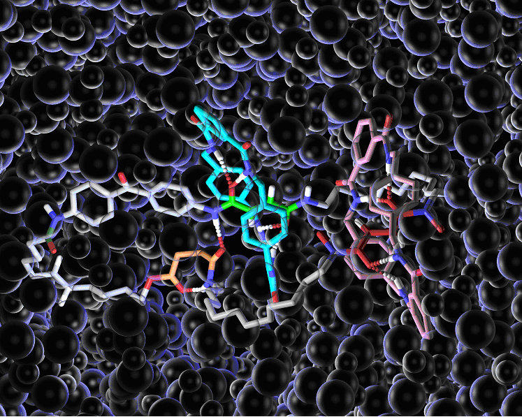
Figure 1.Chemical structure of a mechanically-interlocked rotary molecular motor. Hydrogen bonds are shown by dotted lines. The ‘bubbles’ are solvent molecules (dichloromethane).
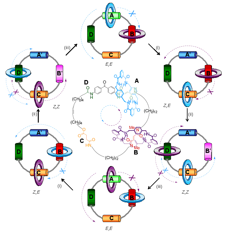
Designing components for ‘molecular machines’ is not always an intuitive process, because the physics that governs how things behave at the molecular level is very different from the physics of our macroscopic world. In the ‘real world’ machine parts (cogs, flywheels, pistons etc) do not move unless and until a force is applied to make them do so. At the molecular scale, however, molecules and their parts are constantly moving above -273 degrees Centigrade (absolute zero) and it is finding ways to control this motion which is the key to developing working mechanical molecular machines. The motor designed by the Edinburgh and Bologna chemists uses hydrogen bonds – the molecular forces used by nature to hold together proteins and DNA – as a ‘glue’ to stop the movement of molecular-sized components when they are not required to move. The molecular motor consists of two small molecular rings linked onto one larger ring and held in place at predetermined sites (‘stations’ A-D below) by hydrogen bonds. The small rings are made to move around the big ring by illuminating them with light of different wavelengths, fuelling chemical reactions that break the hydrogen bonds. Then each small ring blocks one direction of motion of the other ring meaning that both rings move round the large ring in the same direction forming a light-driven directional rotary motor.

Exactly how does it work? Initially the blue and purple rings are glued by hydrogen bonds to the A and B stations. When long wavelength ultraviolet light is shone (shown as process (i) on the diagram) on the molecule A changes to A' and the hydrogen bond glue between the blue ring and the A-station is broken and the blue ring becomes free to move. However, it can only move counter-clockwise because the purple ring blocks movement in the clockwise direction! When the blue ring arrives at C it is stuck there again by hydrogen bonds. Next, process (ii) is brought about by irradiation with short-wavelength ultraviolet light transforming B station into B' and breaking the hydrogen bonds between the purple ring and station B. The purple ring is then able to move until it is ‘captured’ by hydrogen bonds at station D. However, once again it can only move in an counter-clockwise direction to get to D because the clockwise path is blocked by the blue ring at C. White light then changes A' back to A and B' back to B (process (iii)) and so the purple ring moves to A and the blue ring to B, again in a unidirectional manner. Effectively the small rings have now swapped places by following each other halfway around the big ring. In order to complete the rotation of both small rings, processes (i)-(iii) have to be repeated!
Ways to utilize artificial molecular level motors have still to be developed, but possible future applications could include (a) molecular ‘winches’ which could wind up molecular chains (polymers) resulting in length or shape-changes to materials on demand, or (b) the use of molecular rotary motors to power the movement of objects across surfaces (for example, along a path drawn with a laser pointer).
